To design and model a parametric press-fit construction kit.
To design and cut a design using a vinyl cutter.
Understanding KERF (Updated)
Kerf is defined as the width of material that is removed by a cutting process.
Kerf can also be better understood on this link, Kerf and Nesting Margins
I did a test cut on arcylic and MDF material to determine the width of the cut; the width of the laser cutting beam. I used drew a simple 30mm by 30mm square. The pictures below will showed the different cutting of the materials mentioned. The laser machine used was a Epilog 60 Watts, settings were as followed, Speed = 20, Power = 85.
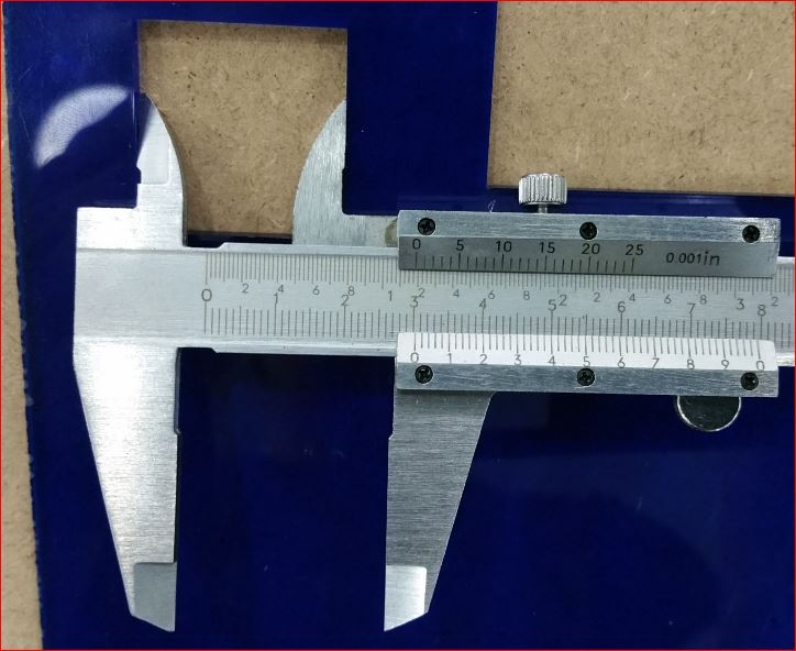
Arcylic Box
ArcylicSquare
The width of the arcylic box was measured at 30.3 mm and the square at 30.1mm
Therefore the difference between them is 0.2mm, per side will be 0.1mm.
If I am using arcylic for joint, then width of the slot will have to have to 0.1 narrower and finger width will have to 0.1 wider.
In this way I will have interferance fit and the joint will press fit snuggly.
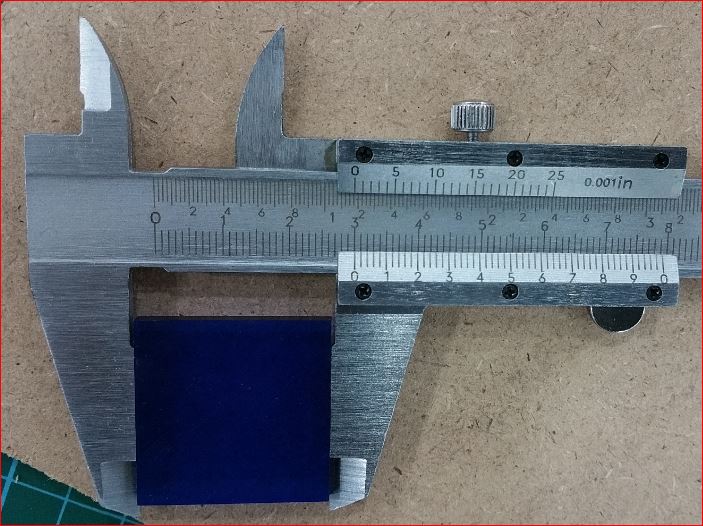
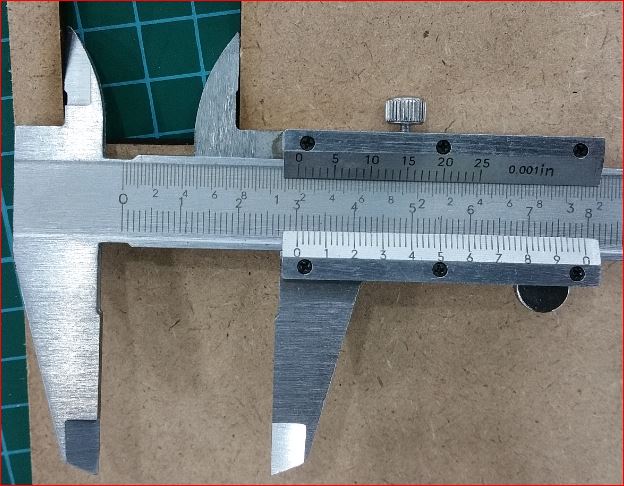
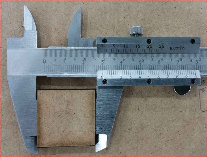
MDF Box
MDF Square
The width of the arcylic box was measured at 30.34 mm and the square at 29.9mm
Therefore the difference between them is 0.44mm, per side will be 0.22mm.
If I am using MDF for joint, then width of the slot will have to have to 0.22 narrower and finger width will have to 0.22 wider.
In this way the interferance fit for the MDF joint will press fit snuggly.
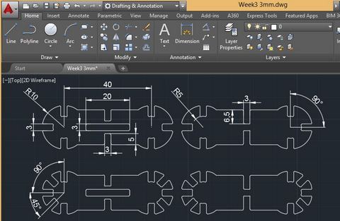
First Press-Fit Construction Design Phase
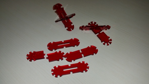
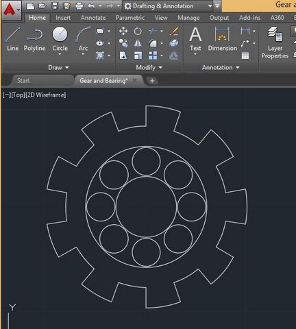
I used AutoCad to design a dog bone joint as shown below and laser cut it using 3mm acrylic to test the design. It was just to experiment with the design and observe how the joint would turn out.
Alas, the design failed. First issue was the interference fit design became a loose fit.
Second, the sectional cross joint was too loose and could not be locked into position.
Lastly, the material snap easily.
Failed Joints Design
Therefore, the design was scape and another design was drawn up.
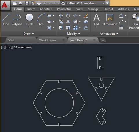
Second Press-Fit Construction Design Phase
Decided to design a lamp cover using Medium-density fibreboard - MDF of 3mm thickness.
The design came from an inspiration found on the internet. Click here to see inspiration
Parameterization consists of applying geometric and dimensional constraints to a drawing to define the geometry and measurements. It makes a drawing easier and practical to edit dimensions without changing its shape because its measurements linked in relatiobship to that drawing.
How Parametric would had help me
I didn't use the parametric constraints when I first started drawing. If I had used this function then, then I would have a breeze to edit the Dog Bone Joint design. I realized I could not only be able to change the length of the lines in the XY direction, I could also changed the thickness of the drawing. When I first started drawing the dog bone joint design, I basically had to change the line one at a time manually. But anyways, I will employ this method on the rest of the upcoming joint design drawings.
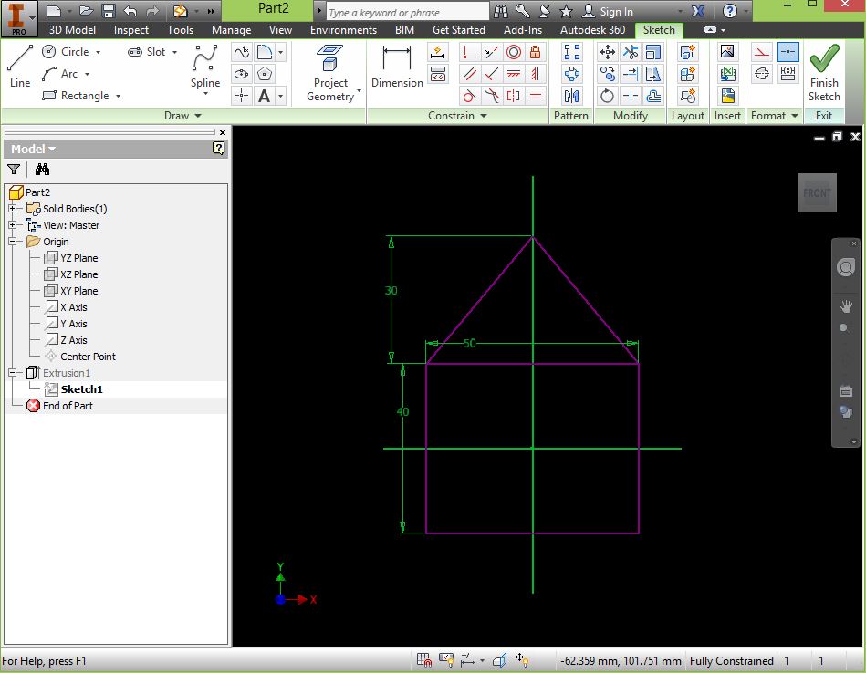
How I would use Parametric (Update)
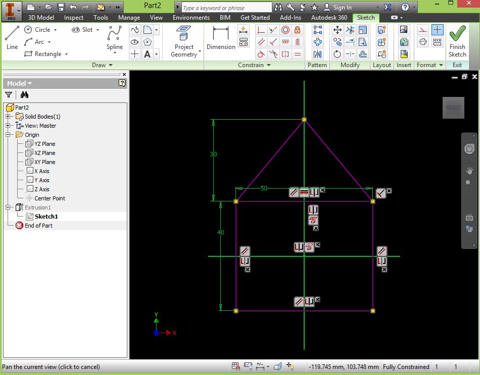
I used Inventor as adviced my colleague Hendra, to drawing simple square box with a triangle on top of it with his guidance.
1. Parametric
Then I added constraints onto the drawing.
2. Parametric
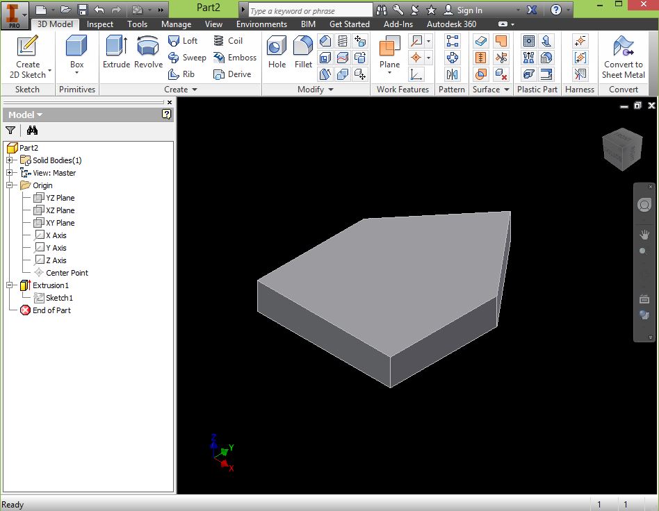
The designed was extructed to form a 3D shape.
3. Parametric
Now I when change the dimension or dragged the constraint of the drawing, noticed the triangle shape had changed but not the square box. It was because I added constraints in relationship to the triangle but I fixed constraint of the square box. Therefore, when I dragged the constraints of the triangle, the geometry of the square box remained unchanged. Of course it can also happened vice versa.
4. Parametric
The working file can be download here (Right click and save link as)
A short video on the parametric design
Press-Fit Construction Production Phase
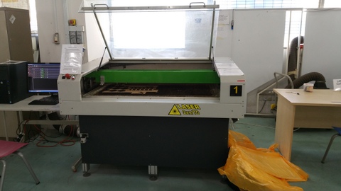
The EAS 70 laser cutting machine was used as choice to cut out the design.
EAS Laser Cutter
In the begining, the joints were too loose when fitted together. It was discovered that the combination of laser power and travel speed contributed to these errors. If the duration of the cut was too long, it would surely resulted in undercut. Therefore the gap of the joints would becomes too big.
Finally the settings for the cutting after some fiddling and trials and errors were as follows.
Laser Line Setting
Laser settings are as follows: Power = 100 and Speed = 45
EAS cutting in action
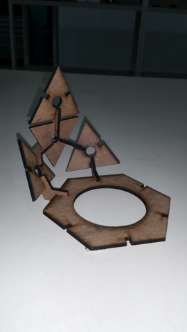
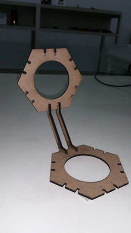
Lamp Cover Assembly
It's assembly time after all the pieces were cut.
Lamp Cover Construction
This is the final assembly.
Final Lamp Cover
Further experiment on another laser cutter
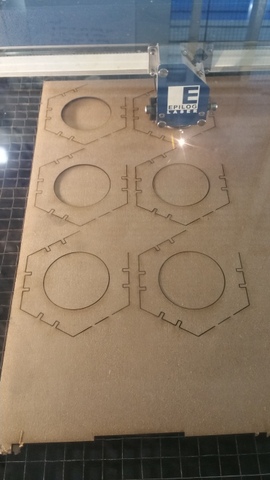
I designed another press fit construction with minor variant. The purpose is try to use another laser cutter; Epilog 60 watts.
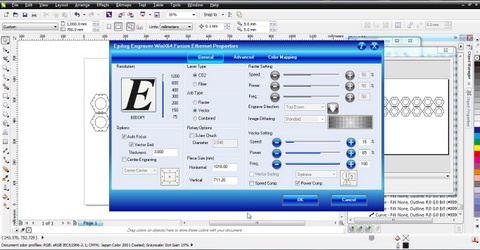
The settings were as follows after same encounters with EAS70 through trials and errors.
Epilog setting
Laser setings are as follows: Power = 100 and Speed = 25
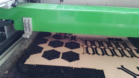
Epilog Cutting Action
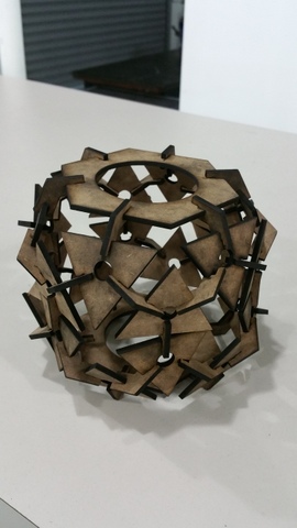
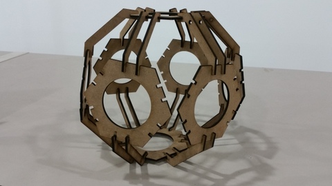
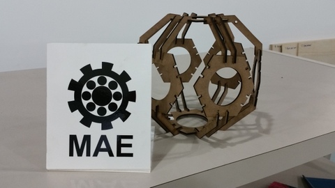
The cut out pieces were then removed and assembled. Sphere Construction
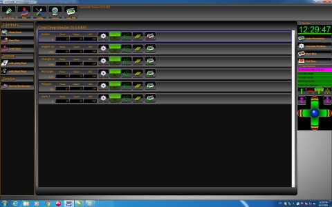
Then I used Coral Draw to import the drawing and added the MAE letters under the design.
It's also easier to manipulate the letters in Coral Draw.
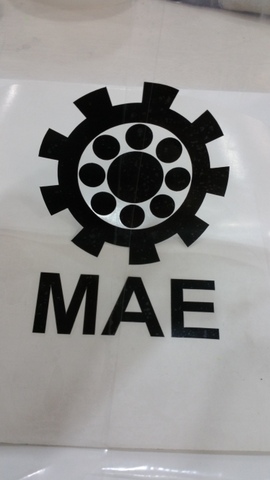
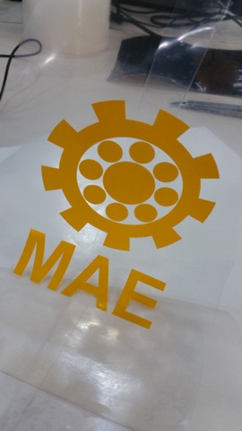
Design Cutting and Transfer
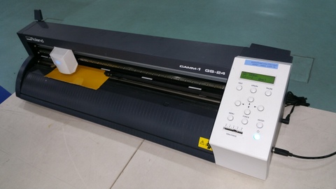
Roland GS-24 vinyl cutter was used cutting out the design.
Roland GS24
The design was cut out on a black colored decal material and the other on yellow.
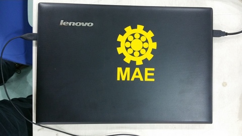
Where I used it
The yellow decal was pasted on the top of my laptop and the black decal was used as a name plate for another design on the press-fit construction.
My comments
It is important to try the various laser cut settings on the same material where it is less conspicuous before doing the actual cut.In this way, material would not be wasted unnecessarily. I found a easy way locate the design on the laser cutter. Simply draw a hairline box to surround the design and run it on laser cutter with power setting at zero and speed at max. In this way, you not only will know the location of the design but also whether there are enough space for the design to be cut.